
Compressed air leaks are one of the biggest hidden cost drivers in production companies. For this reason, compressed air leakage detection is carried out at regular intervals in many companies. However, such actions are time-consuming and often very unpopular with the responsible employees, since reliable leak detection is usually only possible when production is at a standstill (noise level). This can be remedied by automating compressed air leakage detection.
Anyone who has ever dealt with the topic of compressed air leaks knows the example calculations of how expensive a leakage of X mm will be extrapolated to one year. At the same time, everyone who has already carried out a leak detection knows the difficulties and problems that can arise and is aware of the time required (and possible time period – often at the weekend) for this measure. The performance of compressed air leak detection is therefore considered a very unpopular task.
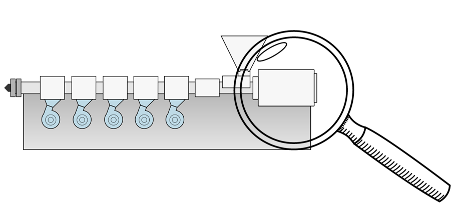
In the case of compressed air leakage detection, the entire compressed air system, i.e. both the generators and the pipeline network as well as all consumers, are checked for leaks. This is done either with the help of your own ear or alternatively with the help of special ultrasonic measurement technology. Without ultrasonic measurement technology, it is very advisable to select a time at which the noise level in production is very low. If the ambient noise is low enough, larger leaks can be detected by their characteristic hissing or whistling. For this reason, the production edge times (before the start of production or after the end of production) and production-free weekends are often used. Of course, this makes the location task even less attractive for the affected employee and often leads to a quite positive result (few leaks) according to the motto “nothing found -> early closing time”. Exactly this initial situation led in a real case known to us to the fact that in a production company the opinion was anchored to operate an almost perfectly maintained compressed air system, although real measurements have revealed the opposite…
Leakage marking always double
If a leakage is detected, it should of course also be marked immediately, so that later detection is easily possible. If possible, the marking should be done in at least double form. A colour marking directly at the point where the leakage was detected (e.g. with adhesive tape) has proven to be useful.
It also makes sense to use different colours, whereby the colour says something about the severity of the leakage:
- green: small leakage
- yellow: medium leakage (e.g. audible with bare ear)
- red: severe leakage (e.g. noticeable draught)
- Blue: Leakage not exactly detected, but suspected
In addition, it has proven useful to place a second marking at a central point of the extrusion line (e.g. at the extruder controller) for each leakage detected. Maintenance does not have to run the entire line to find a mark, but can read directly at the extruder control that there are X leaks on this line and can also immediately see the severity of the leaks.
As a further measure, the marking of any leakage in a hall plan is highly recommended. A simple cross at the respective point makes the later search for “markings” much easier.
The methodology described above clearly shows that compressed air leak detection can be a time-consuming process. Especially when compressed air networks are in relatively good condition, the detection of leaks becomes all the more difficult, but at the same time the potential for savings is smaller. Especially then it should be tried to enable an efficient method for system monitoring.
3 simple ways to detect compressed air leaks
Various methods can be used to manually determine the quantity of compressed air leaks quickly and cost-effectively, for example to select the correct time for the leakage location described above. In this case, there is no fixed frequency for a leakage location, but a weekly (e.g.) determination of the leakage quantity is carried out by one of the methods listed below. If a defined limit value is exceeded, a leakage location can be planned.
- pressure drop measurement
- load profile analysis (energy monitoring)
- volume flow measurement
A very simple method is the method of pressure drop measurement. While all compressed air consumers in production are out of operation, the compressed air reservoir is brought to the upper cut-off pressure (e.g. 8.5 bar). Now the compressor can be switched off so that the pressure-tank is not recharged. After a defined time (e.g. 15min) the pressure is read off again at the pressure gauge of the pressure accumulator.
The pressure drop per unit of time is calculated from these values and the leakage quantity per unit of time is determined taking into account the network volume (storage tank + pipe network). From this value, a value for the annual costs of the leakage can even be determined for a known specific compressor capacity.
The prerequisites for carrying out this method are almost everywhere, as only a clock and a manometer are required here.
Energy consumption meters are used in the load profile analysis, which are already available in very many cases anyway. The energy consumption that occurs during a production standstill phase (i.e. only the leaks are “diligent”) is measured. The compressor must not be switched off for this, of course, as otherwise no replenishment would take place.
With this method, the compressor is not switched off after production has been completed. At the same time, the energy consumption of the compressor is read from the consumption meter (active energy meter) and noted with an associated time. After a representative period of time, the energy consumption and the time are noted again. It is important that the time period is selected so long that compressors operating in stages have switched on and off several times.
The prerequisites for carrying out this method are also almost everywhere, since only a clock and an energy consumption counter are necessary.
Another method is the measurement of the volume flow. However, this requires additional measurement technology (volume flow measurement). With this method, a volume flow meter is integrated into the outgoing volume flow of the compressed air compressor, which determines the flow rate per time unit and can often already calculate an average value independently. If this value is combined with an electrical load profile analysis, a specific compressor characteristic value (kWh/Nm³) can be formed for different compressor operating points.
Automation of leak detection
Of course, the methods mentioned above can nowadays also be carried out automatically. For automation, the characteristic values recorded by the sensors (pressure, volume flow, electrical load curve, times, etc.) are combined in a central evaluation system. There the formulaic connections and algorithms are stored and an automatic reporting is configured (if no prefabricated block for the automated leakage analysis is available).
 Virtually any conceivable freely programmable PLC system can be used for control, regulation and evaluation.
The following explanations refer specifically to the implementation with a plusMETER/plusWARE solution from SHS plus GmbH, but can also be transferred to systems such as Beckhoff, B&R, Siemens, IBA, Wago, etc. in the same way.
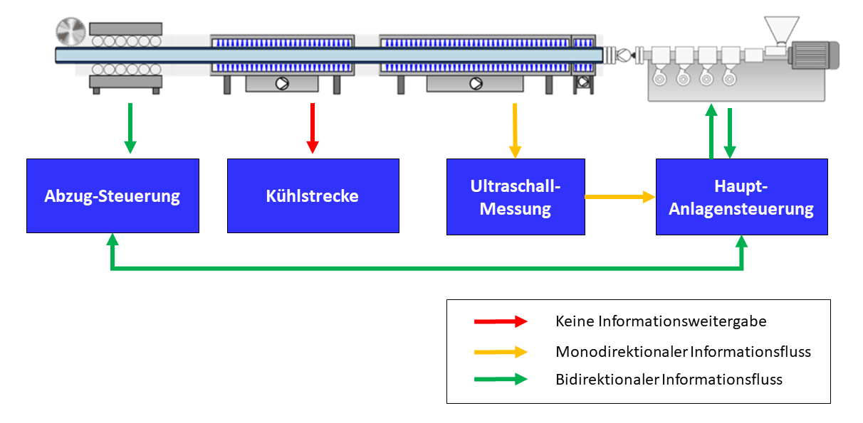
In automated compressed air leakage assessment, a central unit functions as a control, evaluation and reporting system.
As shown in the diagram, the central control unit (here a plusMETER central unit) is connected.
- with an air flow rate sensor,
- an electrical power measurement at the air compressor,
- pressure measurement in the compressed air reservoir,
- a way to access data storage (e.g. SQL) on the network or in the cloud,
- internet access for sending e-mails
And, if necessary, additionally with actuators for
- automatic activation or deactivation of the compressor and
- servo valves for opening and closing individual compressed air areas.
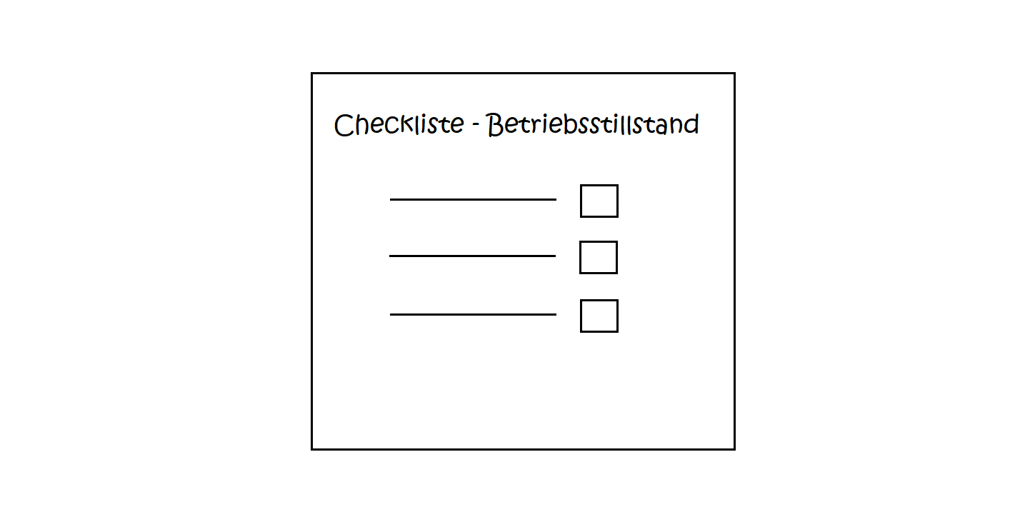
The central control unit is programmed for automated compressed air leak detection in such a way that the leakage evaluation is carried out automatically in a preset cycle (e.g. always on weekends). Before the sequence is started, however, the system automatically determines whether production has actually stopped (e.g. via the air mass flow sensor) or whether a weekend production may exceptionally take place.
Provided that the analysis does not endanger the production operation, the system starts the analysis. For this purpose, the measurement methods described above are carried out automatically. In addition, actuators access different servo valves and thus block off different production and storage areas one after the other. This method helps to assign the leaks to individual local areas and reduces the effort involved in searching for actual leakage locations.
After completion of the analysis, the system can create an automatic report which can be sent immediately to maintenance or the energy management representative so that leaks can be rectified at short notice.
Due to the automation it is possible to have the analysis carried out at very frequent times (e.g. every night in one-shift operation), so that new leaks can be recorded very quickly and localised very quickly due to the allocation to individual production areas.
Exemplary evaluation graphics for an automated leakage analysis:


If you are interested on being kept informed about new articles or other updates, please feel free to register for our newsletter and gain access to our free download section with interesting tools.


