When manufacturing profiles (with hollow chamber structures), the design of the vacuum calibrations and the post-cooling represents a challenge. The number of calibrations, the geometry, the materials and coatings used, the vacuum control, the temperature control and much more must be optimally tailored to the product, the material and the target production speed. With modern simulation methods, the design process and the resulting target process can be optimized. A key factor for the use of simulation-based design are exact thermomechanical material models (density, heat capacity, thermal conductivity vs. temperature).
Plastic profiles that have one or more chambers on the inside that enclose air are referred to as hollow chamber profiles. The figure below shows a PMMA glazing bead profile with three hollow chambers. In the following, the profile is used as an example for the design of the cooling section.

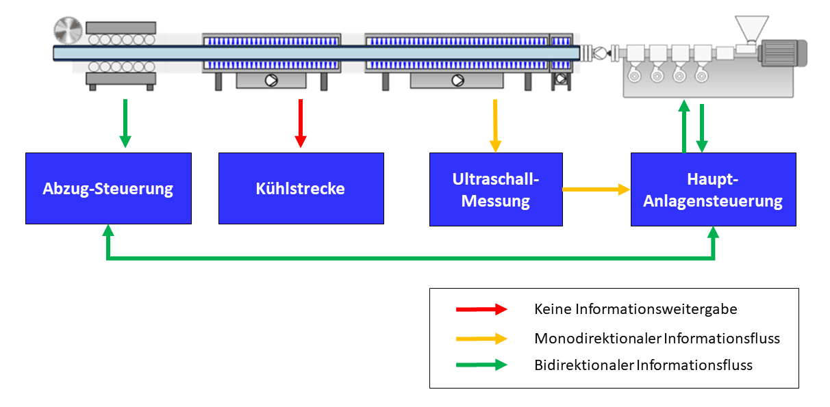
The profile is to be produced on an existing cooling line (see illustration). The calibration table is 6m long in total and can be flexibly equipped with several vacuum calibrations. A standardized length of 250mm each is taken as the individual length for hollow chamber profiles. Standard lengths are often used to optimize the manufacturing and setup process. The remaining post-cooling distance (immersion bath), when using four calibrations with 50mm length each, is thus approx. 5m.

In the design process, modern simulation systems such as the chillWARE® system can support optimal process design. Existing or newly developed cooling lines can be created as a digital twin in the simulation environment via an intuitive graphical user interface. As simulation results, for example, the
- temperature distribution of the profile and the air in the hollow chambers,
- shrinkage and warpage,
- the thermal performances and the
- the necessary cooling water flow rates
can be determined in any area of the cooling section.
An important question at the beginning of the design process is the achievable production speed on the line. A central limiting factor in the cooling section is the dimensional stability of the profile after the last calibration as well as in the haul-off and in the saw. A hotspot temperature of 60°C on the inner webs of the profile after leaving the calibration table and before entering the fume cupboard is initially defined as a critical limit value for the present profile. The melt temperature (245°C) and the cooling water temperatures must be specified. The production speed that can then be achieved is determined exactly and fully automatically with an optimizer. In the example presented here, a maximum production speed of 3.0 m/min is initially determined under the given boundary conditions. The following figure shows the characteristic temperatures over the entire extrusion process. The position in the process at which the target value of the optimization (hotspot<60°C in the entire cross-section) is reached is marked with the vertical green line.

The temperature distribution after leaving the calibration table and the remaining shrinkage up to the cold profile (25°C) are shown in the following figures. The hotspot is 61.4°C – as expected – at the inner bars. The resulting shrinkage in these areas is greater than in the rest of the profile.


In the further course of the process design, the thermo-mechanical conditions in the calibration should now be analysed more precisely. Central questions are, for example, as follows:
- How many calibrations must be used at the target speed?
- Which temperatures should be set?
- How must the allowances or the contour geometries be designed?
- What cooling capacities are dissipated in the calibrations and how high should the realized water volume flows be?
Material-specific thermal parameters can be used for the design. The heat deflection temperature (1.80 MPa) of the PMMA used here is 95°C according to ISO 75-1/-2. The glass transition temperature is 112°C according to ISO 11357-1/-2 and the VICAT softening point according to ISO 306 is 103°C.
Since PMMA has a high modulus of elasticity of 3,200 MPa, the risk of internal stresses and stress cracks is particularly high in the case of inhomogeneous cooling. A compromise must therefore be found between cooling that is as gentle and homogeneous as possible and cooling that is as fast as possible or the high production speed that is achieved. In the present case, the calibrations are tempered at [60, 40, 20, 20] °C, so that sufficient cooling can be achieved and the temperature gradient in the profile cross-section reduced. A common method of reducing residual stresses is inline annealing with hot air ovens or IR emitters. This procedure can also be tested with chillWARE® if required.
After leaving the last calibration, there should be sufficient dimensional stability. The detailed analysis shown below after leaving the last calibration shows that the average temperature of the profile is already 62.8°C. The free webs have already cooled down completely and the basic contour is sufficiently stable. Only the not directly cooled inner bars are still hot. The remaining free uniaxial thermal shrinkage until the profile has cooled completely is a very low 0.09%, so that no pronounced distortion phenomena are to be expected.


One way to reduce the differences is active internal cooling with air. This process can be tried out virtually with chillWARE®. The air chamber temperatures shown in the following figure show that the air temperatures first very quickly adopt the average inner wall temperatures in the respective hollow chambers and then slowly cool down with the profile. The air in the hollow chambers is cooled by the cold outer structures of the profile, the hot inner bars are then in turn cooled by the air. As a result, the air in the central hollow chamber remains longer at a higher temperature level, since it is only cooled here from two and not from three sides. To eliminate this inhomogeneity, an active cooling air volume flow can be introduced into the middle chamber.

The free uniaxial and surface shrinkage as well as the resulting width and height of the profile can be analysed at any position in the process with chillWARE®. This important information can be used in calibration design to determine the optimal geometric contour for each calibration. The aim should be to adapt the calibration contour to the determined free shrinkage, so the lowest external forces on the profile arise. A gentle, internal stress-free cooling can be favoured in this way.

In the case of hollow chamber profiles in particular, the cooling and thus also the shrinkage cannot be implemented homogeneously at every point in the process. As a result, individual areas in the profile have to be considered differently in the design. The analysis of the shrinkage distribution at the outlet of the second calibration shown in the following figure clearly shows these inhomogeneities. In the area of the free webs in the edge areas, there is only a shrinkage of approx. 0.34% compared to the nominal size, in contrast to this, the inner webs in the hollow chambers shrink by approx. 7.5% in area and 3.7% in wall thickness. The circumferential contour shrinks by approx. 1.4% in area and 0.65% in wall thickness.

Furthermore, it can be determined which areas of the calibration can already be released in order to avoid unnecessarily high pull-off forces or even to provoke jamming. The analysis of the temperature distribution after the third calibration shows that the temperatures of the free inner bars are already around 28-32°C, so that these areas can be freed in the fourth calibration.

The cooling capacities to be dissipated and the water flow rates required – based on a temperature difference between flow and return of 2°C – are summarized in the following diagram. Basically, it can be observed in profile extrusion that the highest thermal output is already dissipated in the first calibration. In the present case, it is 7.2 kW of the total 21.8 kW to be dissipated. To dissipate this high thermal output, it is necessary to equip the first caliber with conformal cooling and a water flow rate of 52 l/min.

With modern simulation systems, such as chillWARE®, the design of the cooling and tempering processes of (co-)extruded complex profiles can be supported in a targeted manner. The use of simulation methods reduces development time and costs and significantly increases energy and resource efficiency.
You are welcome to contact us if you have specific individual problems on this topic!


