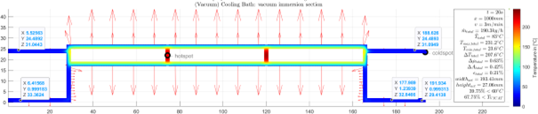
When producing profiles and tubes with internal hollow chamber structures, so-called supporting air is often used. Here, a volume of air is blown through the die into the interior of the hollow chambers or lumens so that they do not collapse. The outer surfaces of the extrudates are usually drawn to the surfaces of the calibration by means of negative pressure (vacuum). However, the chambers inside the extrudates cannot be reached in this way, so controlling the internal geometry during the cooling process is a major challenge. Active control of the supporting air flow rate or internal pressure in the individual chambers with suitable hardware and software is a tried and tested approach to solving this problem.
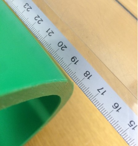
Hollow chamber profiles are plastic profiles that have one or more chambers inside that enclose air. The following illustration shows an exemplary profile geometry. The left picture shows the desired geometry of the profile. The inner areas of the profile are usually not calibrated, as conventional calibrations only specify the contour of the outer surface. Thus, in practice, a multitude of disturbances can occur and thus significantly influence the shape and position of the inner ridges. These influences are exemplarily shown in the middle and right picture. The disturbance sizes include, among others:
- Low fluctuations in the mass throughput of the extruder
- Variations in the flow properties of the polymers
- Change in the temperature of the supporting air
- Change in the volume flow of the supporting air because channels are blocked by deposits or melt splashes
- Influence of gravity, also dependent on the orientation of the die
- Fluctuations of the internal pressure due to the cutting processes

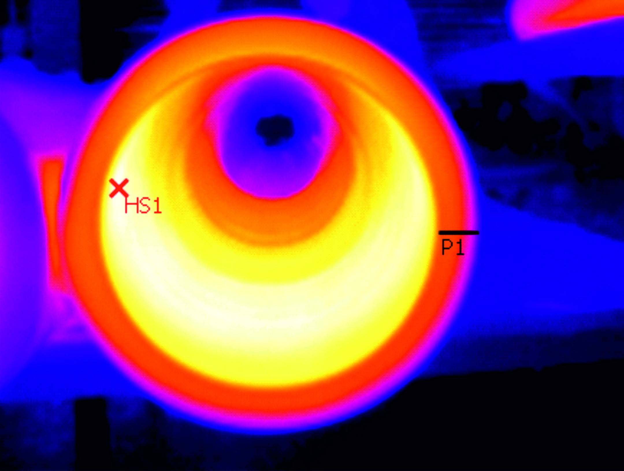
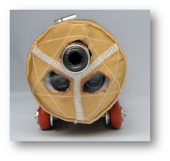
These statements can thus also be transferred to the production of tubes with different chambers (multi-lumen tubes). The same mechanisms and disturbance variables are involved. Analogous to the above description, the possible influences are shown in the following figure.

In practice, different strategies are pursued to eliminate the various disturbing influences. To compensate for the influence of gravity, the flow channels inside the mould are sometimes provided with a crown in the opposite direction to the sagging of the horizontal webs. Regardless of how the inner webs are aligned, it is possible to influence the position or contour of the inner webs by manually providing supporting air. If it is only possible to control the supporting air (e.g. via a manually operated pressure reducer), the correct setting is usually searched for iteratively during the start-up process and this setting is then only checked by measuring the inner webs as part of quality inspections. The major disadvantage of these approaches is that faults that occur during production cannot be automatically corrected. In most cases, they only become apparent after some time and have to be eliminated through an iterative process. It is easy to imagine that this can lead to high reject rates and have a negative impact on process stability.
If, the supporting air or the internal pressure in the individual hollow chambers is continuously adjusted, an almost constant contour or geometry of the inner webs can be guaranteed. The following illustration shows the basic structure of such systems.

The continuous measurement of the local air pressures and volume flows in the individual chambers is used to set up a closed control loop using modern piezo-electric proportional control valves as actuators. Depending on the specific implementation, it is thus possible to control either an internal pressure that is as constant as possible in each individual chamber, or a volume flow that is as constant as possible. The choice of which value should be specified as the setpoint depends on the specific application. One of the advantages of modern systems for supporting air control is that it is possible to switch between the two scenarios as desired. For example, in dynamic processes with high extrusion speeds and short semi-finished product lengths, it makes sense to regulate the internal pressure of the chambers. As a rule, these processes are dominated by the closing of the hollow chambers at the moment of cutting. With larger profiles, however, it is usually more expedient to specify the volume flow, as this can also be calculated very precisely in theory during tool and calibre design. This then has a clear advantage when it comes to the number of iteration loops during sampling.
The following figure shows an exemplary visualisation of such a system. The additional recording and graphic representation of the measured values (pressure and volume flow) provide further possibilities for assessing process stability and documentation.

If you are faced with the challenge of being able to produce the geometry of inner webs or individual lumens precisely, stably and reproducibly, you should consider the possibility of automated control of the supporting air.
Please feel free to contact us if you have specific individual problems on this topic!
Register here (free of charge) as a premium member and gain access to our download area. There you will different tools, checklists, etc. In addition, as a Premium user you will always be informed about new contributions.


